Senin, 31 Maret 2008

Configuring the Default Route

You can see two dynamic (D) kernel (K) routes, which have been added automatically when the addresses were added:

[MikroTik] ip route> print                                                    
Flags: X - disabled, I - invalid, D - dynamic, R - rejected
# TYPE DST-ADDRESS NEXTHOP-S... GATEWAY DISTANCE INTERFACE
0 D connect 192.168.0.0/24 A 0.0.0.0 0 Local
1 D connect 10.1.1.0/24 A 0.0.0.0 0 Public
[MikroTik] ip route> print detail
Flags: X - disabled, I - invalid, D - dynamic, R - rejected
0 D dst-address=192.168.0.0/24 gateway=0.0.0.0 nexthop-state=A
preferred-source=192.168.0.254 interface=Local distance=0 type=connect

1 D dst-address=10.1.1.0/24 gateway=0.0.0.0 nexthop-state=A
preferred-source=10.1.1.12 interface=Public distance=0 type=connect

[MikroTik] ip route>

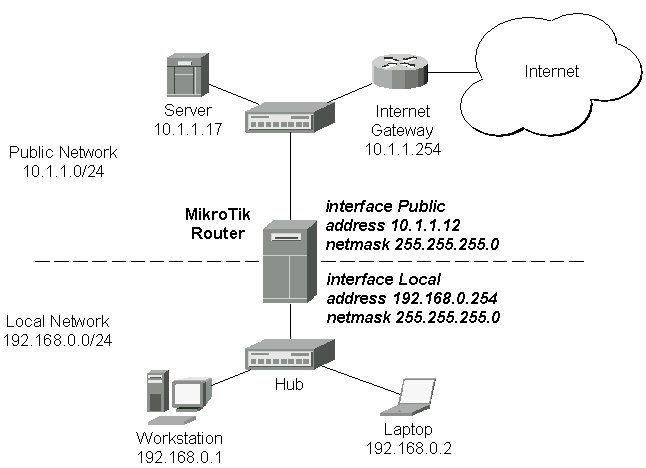
These routes show, that IP packets with destination to 10.1.1.0/24 would be sent through the interface Public, whereas IP packets with destination to 192.168.0.0/24 would be sent through the interface Local. However, you need to specify where the router should forward packets, which have destination other than networks connected directly to the router. This is done by adding the default route (destination 0.0.0.0, netmask 0.0.0.0). In this case it is the ISP's gateway 10.1.1.254, which can be reached through the interface Public:

[MikroTik] ip route> add gateway=10.1.1.254      
[MikroTik] ip route> print
Flags: X - disabled, I - invalid, D - dynamic, R - rejected
# TYPE DST-ADDRESS NEXTHOP-S... GATEWAY DISTANCE INTERFACE
0 static 0.0.0.0/0 A 10.1.1.254 1 Public
1 D connect 192.168.0.0/24 A 0.0.0.0 0 Local
2 D connect 10.1.1.0/24 A 0.0.0.0 0 Public
[MikroTik] ip route>

Here, the default route is listed under #0. As we see, the gateway 10.1.1.254 can be reached through the interface 'Public'. If the gateway would have been specified incorrectly, the value for the argument 'interface' would be unknown. Note, that you cannot add two routes to the same destination, i.e., destination-address/netmask! It applies to the default routes as well. Instead, you can enter multiple gateways for one destination. For more information on IP routes, please read the relevant topic in the Manual.

If you have added an unwanted static route accidentally, use the 'remove' command to delete the unneeded one. Do not remove the dynamic (D) routes! They are added automatically and should not be deleted 'by hand'. If you happen to, then reboot the router, the route will show up again.

Selasa, 18 Maret 2008

Adding Addresses

Assume you need to configure the MikroTik router for the following network setup:


Please note that the addresses assigned to different interfaces of the router should belong to different networks. In the current example we use two networks:

  • The local LAN with network address 192.168.0.0 and 24-bit netmask 255.255.255.0 The router's address is 192.168.0.254 in this network.
  • The ISP's network with address 10.1.1.0 and 24-bit netmask 255.255.255.0 The router's address is 10.1.1.12 in this network.
The addresses can be added and viewed using the following commands:

[MikroTik] ip address> add address 192.168.0.254/24 interface Local
[MikroTik] ip address> add address 10.1.1.12/24 interface Public
[MikroTik] ip address> print
Flags: X - disabled, I - invalid, D - dynamic
# ADDRESS NETWORK BROADCAST INTERFACE
0 192.168.0.254/24 192.168.0.0 192.168.0.255 Local
1 10.1.1.12/24 10.1.1.0 10.1.1.255 Public
[MikroTik] ip address>

Here, the network mask has been specified in the value of the address argument. Alternatively, the argument 'netmask' could have been used with the value '255.255.255.0'. The network and broadcast addresses were not specified in the input since they could be calculated automatically.


Mikrotik : Working with Interfaces

Before configuring the IP addresses and routes please check the '/interface' menu to see the list of available interfaces. If you have PCI Ethernet cards installed in the router, it is most likely that the device drivers have been loaded for them automatically, and the relevant interfaces appear on the '/interface print' list, for example:

[MikroTik] interface> print                                                   
Flags: X - disabled, D - dynamic
# NAME MTU TYPE
0 X ether1 1500 ether
[MikroTik] interface>

The device drivers for NE2000 compatible ISA cards need to be loaded using the 'add' command under the /drivers menu. For example, to load the driver for a card with IO address 0x280 and IRQ 5, it is enough to issue the command:

[MikroTik] driver> add name=ne2k-isa io=0x280                                      
[MikroTik] driver> print
Flags: I - invalid, D - dynamic
# DRIVER IRQ IO MEMORY ISDN-PROTOCOL
0 D PCI NE2000
1 ISA NE2000 280
[MikroTik] driver>

The interfaces need to be enabled, if you want to use them for communications. Use the '/interface enable name' command to enable the interface with a given name, for example:

[MikroTik] interface> print                                                   
Flags: X - disabled, D - dynamic
# NAME MTU TYPE
0 X ether1 1500 ether
1 X ether2 1500 ether
[MikroTik] interface> enable 0
[MikroTik] interface> enable ether2
[MikroTik] interface> print
Flags: X - disabled, D - dynamic
# NAME MTU TYPE
0 ether1 1500 ether
1 ether2 1500 ether
[MikroTik] interface>

You can use the number or the name of the interface in the 'enable' command.

The interface name can be changed to a more descriptive one by using the '/interface set' command:

[MikroTik] interface> set 0 name=Public                                           
[MikroTik] interface> set 1 name=Local
[MikroTik] interface> print
Flags: X - disabled, D - dynamic
# NAME MTU TYPE
0 Public 1500 ether
1 Local 1500 ether
[MikroTik] interface>

Use of the 'setup' Command

The initial setup of the router can be done by using the '/setup' command which enables an interface, assigns an address/netmask to it, and configures the default route. If you do not use the setup command, or need to modify/add the settings for addresses and routes, please follow the steps described below.

Navigating the Terminal Console

After logging into the router you will be presented with the MikroTik RouterOS Welcome Screen and command prompt, for example:

  MMM      MMM       KKK                          TTTTTTTTTTT      KKK
MMMM MMMM KKK TTTTTTTTTTT KKK
MMM MMMM MMM III KKK KKK RRRRRR OOOOOO TTT III KKK KKK
MMM MM MMM III KKKKK RRR RRR OOO OOO TTT III KKKKK
MMM MMM III KKK KKK RRRRRR OOO OOO TTT III KKK KKK
MMM MMM III KKK KKK RRR RRR OOOOOO TTT III KKK KKK

Mikrotik RouterOS v2.4 (c) 1999-2001 http://www.mikrotik.com/
[MikroTik] >

The command prompt shows the identity name of the router and the current menu level, for example:

[MikroTik] >                          Base level menu
[MikroTik] interface> Interface configuration
[MikroTik] ip firewall static-nat> NAT rule management

The list of available commands at any menu level can be obtained by entering the question mark '?', for example:

[MikroTik] > ?
bridge Bridge settings
driver Driver management
e-mail sending e-mail from router
export print configuration as set of router commands
file Local router file storage.
import Run exported configuration script
interface Interface configuration
ip IP protocol settings
log System logs
password Change password
ping Send ICMP Echo packets
port Serial ports
quit Quit console
redo Redo previosly undone action
restore Restore previously backed up configuration
routing Routing protocol configuration
setup Do basic setup of system
system System information and utilities
tool Diagnostics tools
undo Undo previous action
user User management
[MikroTik] > ip ?
accounting Traffic accounting
address Address management
arp ARP entries management
dhcp-client DHCP client settings
dhcp-server DHCP server settings
dns DNS settings
export print configuration as set of router commands
firewall Firewall management
neighbor Neighbor discovery
packing IP Packet Packing setup
policy-routing Policy routing setup
ppp PPP general settings
queue Bandwidth management
route Route management
service
[MikroTik] >

The list of available commands and menus has short descriptions next to the items. You can move to the desired menu level by typing its name and hitting the [Enter] key, for example:

[MikroTik]>                      Base level menu
[MikroTik]> driver Enter 'driver' to move to the driver level menu
[MikroTik] driver> / Enter '/' to move to the base level menu from any level
[MikroTik]> interface Enter 'interface' to move to the interface level menu
[MikroTik] interface> /ip Enter '/ip' to move to the IP level menu from any level
[MikroTik] ip>

A command or an argument does not need to be completed, if it is not ambiguous. For example, instead of typing 'interface' you can type just 'in' or 'int'. To complete a command use the [Tab] key.

The commands may be invoked from the menu level, where they are located, by typing its name. If the command is in a different menu level than the current one, then the command should be invoked using its full or relative path, for example:

[MikroTik] ip route> print                  Prints the routing table
[MikroTik] ip route> .. address print Prints teh IP address table
[MikroTik] ip route> /ip address print Prints teh IP address table

The commands may have arguments. The arguments have their names and values. Some arguments, that are required, may have no name. Below is a summary on executing the commands and moving between the menu levels:

       Command                               Action
command [Enter] Execute the command
[?] Show the list of all available commands
command [?] Display help on the command and the list of arguments
command argument [?] Display help on the command's argument
[Tab] Complete the command/word. If the input is ambiguous, a
second gives possible options
/ Move up to the base level
/command Execute the base level command
.. Move up one level
"" Enter an empty string
"word1 word2" Enter 2 words that contain a space

You can abbreviate names of levels, commands and arguments.

For the IP address configuration, instead of using the 'address' and 'netmask' arguments, in most cases you can specify the address together with the number of bits in the network mask, i.e., there is no need to specify the 'netmask' separately. Thus, the following two entries would be equivalent:

/ip address add address 10.0.0.1/24 interface ether1
/ip address add address 10.0.0.1 netmask 255.255.255.0 interface ether1

However, if the netmask argument is not specified, you must specify the size of the network mask in the address argument, even if it is the 32-bit subnet, i.e., use 10.0.0.1/32 for address 10.0.0.1 and netmask 255.255.255.255

MikroTik Wireless Configuration

Setup uses Safe Mode. It means that all changes that are made during setup
are reverted in case of error, or if Ctrl-C is used to abort setup. To keep
changes exit setup using the ‘x’ key.
[Safe Mode taken]

Choose options by pressing one of the letters in the left column, before
dash. Pressing ‘x’ will exit current menu, pressing Enter key will select the
entry that is marked by an ‘*’. You can abort setup at any time by pressing
Ctrl-C.

Entries marked by ‘+’ are already configured.
Entries marked by ‘-’ cannot be used yet.
Entries marked by ‘X’ cannot be used without installing additional packages.
r - reset all router configuration
+ l - load interface driver
+ a - configure ip address and gateway
d - setup dhcp client
+ s - setup dhcp server
p - setup pppoe client
t - setup pptp client
* x - exit menu
your choice:
OR
[admin@MikroTik] > ip address
[admin@MikroTik] ip address> add address=192.168.1.1/24 interface=ether1
[admin@MikroTik] ip address> pr
# ADDRESS NETWORK BROADCAST INTERFACE
0 192.168.1.1/24 192.168.1.0 192.168.1.255 ether1
admin@MikroTik] ip address> /
[admin@MikroTik] >
[admin@MikroTik] >interface
[admin@MikroTik] interface> pr
Flags: X - disabled, D - dynamic, R - running
# NAME TYPE RX-RATE TX-RATE MTU
0 X ether1 ether 0 0 1500
1 X wlan1 wlan 0 0 1500
[admin@MikroTik] interface> enable 0
[admin@MikroTik] interface> enable 1

[admin@MikroTik] interface> pr
Flags: X - disabled, D - dynamic, R - running
# NAME TYPE RX-RATE TX-RATE MTU
0 R ether1 ether 0 0 1500
1 X wlan1 wlan 0 0 1500
[admin@MikroTik] ip address>add address=172.1.2.1/30 interface=wlan1
[admin@MikroTik] interface eoip>
[admin@MikroTik] interface eoip>add name=eoip-tunnel1 remote-address=172.1.2.2 tunnel-id=1 disabled=no arp=enabled
[admin@MikroTik] interface eoip>pr
Flags: X - disabled, R - running
0 R name=”eoip-tunnel1″ mtu=1500 mac-address=FE:FD:00:00:00:00 arp=enabled remote-address=172.1.2.2 tunnel-id=1
[admin@MikroTik] interface eoip>..
[admin@MikroTik] interface>
[admin@MikroTik] interface> bridge
[admin@MikroTik] interface bridge> add name=bridge1
[admin@MikroTik] interface bridge>pr
Flags: X - disabled, R - running
0 R name=”bridge1″ mtu=1500 arp=enabled mac-address=00:00:00:00:00:0 forward-protocols=ip,arp,appletalk,ipx,ipv6,other stp=no priority=32768 ageing-time=5m forward-delay=15s garbage-collection-interval=4s hello-time=2s max-message-age=20s
[admin@MikroTik] interface bridge>port
[admin@MikroTik] interface bridge port>pr
# INTERFACE BRIDGE PRIORITY PATH-COST
0 ether1 none 128 10
1 eoip-tunnel1 none 128 10
2 wlan1 none 128 10
[admin@MikroTik] interface bridge port>set eoip-tunnel1 bridge=bridge1
[admin@MikroTik] interface bridge port>set ether1 bridge=bridge1
[admin@MikroTik] interface bridge port>pr
# INTERFACE BRIDGE PRIORITY PATH-COST
0 ether1 bridge1 128 10
1 eoip-tunnel1 bridge1 128 10
3 wlan1 none 128 10
[admin@MikroTik] interface bridge port>.. ..
[admin@MikroTik] interface>wireless
[admin@MikroTik] interface wireless>set wlan1 mode=bridge disable-running-check=no band=5ghz frequency=5180 ssid=test1
Configurration For Mikrotik Station / Client
[admin@MikroTik] interface eoip>add name=eoip-tunnel1 remote-address=172.1.2.1 tunnel-id=1 disabled=no arp=enabled
[admin@MikroTik] interface wireless>set wlan1 mode=station disable-running-check=no band=5ghz frequency=5180 ssid=test1
[admin@MikroTik] interface>pr
Flags: X - disabled, D - dynamic, R - running
# NAME TYPE RX-RATE TX-RATE MTU
0 R ether1 ether 0 0 1500
1 R bridge1 bridge 0 0 1500
2 R eoip-tunnel1 eoip-tunnel 0 0 1500
3 R wlan1 wlan 0 0 1500


Mikrotik Transparant Proxy

setting transparant web proxy server

1. first se t web proxy
/ ip web-proxy
set enabled=yes –>> to make ip web proxy enable
set src-address=0.0.0.0 –>> to make source address to access web proxy will allow
set port=8080 –>> to make port for web proxy
set hostname=”proxy.war.net.id” –>> setting for visble hostname web proxy
set transparent-proxy=yes –>> make transparant proxy enable
set parent-proxy=0.0.0.0:0–>> if we used parent proxy x
set cache-administrator=”support@somethink.org” –>> make set administrator info support
set max-object-size=4096KiB –>> maximal object can cacth with the proxy server
set cache-drive=system –>> where drive position that cache wil be saved
set max-cache-size=unlimited –>> maximal harddrive we used for cache
set max-ram-cache-size=unlimited –>> maximal ram we used for cache

2. add nat for redirect port for squid to make transparant

/ip firewall nat add chain=dstnat protocol=tcp dst-port=80 action=redirect to-ports=8080 –>> setting can redirect port 80 to 8080 for proxy server
/ip firewall nat add chain=dstnat protocol=tcp dst-port=3128 action=redirect to-ports=8080 –>> setting can redirect port 3128 to 8080 for proxy server
/ip firewall nat add chain=dstnat protocol=tcp dst-port=8080 action=redirect to-ports=8080 –>> setting can redirect port 8080 to 8080 for proxy server

14 Step Configuration of Mikrotik using ADSL

This articel i explain how to configuration mikrotik using pc for router.

1. Configuration position of ADSL connection
modem —Mikrotik—-Switch —– Client
|
Client

a. Modem IP –>> 192.168.1.1

b. Mikrotik Using 2 Interface - Ether1 —->> 192.168.1.2

- Ether2 —->> 192.168.0.254

c. Switch — Client ip 192.168.0.1-253

2. Configuration step router pc mikrotik

a. add ip address to interface 1

/ip address add interface=ether1 address = 192.168.1.1 netmask= 255.255.255.0

b. add ip address to interface2

/ip address add interface=ether2 address = 192.168.0.1 netmask= 255.255.255.0

c. to see input of interface

/interface print

d. Set Value name off interface

/inteface set 0 name=”Public” –>> For Modem
/inteface set 1 name=”Lan” –>> For Lan

e. set routing for net ( modem )

/ip route add gateway=192.168.0.1

f. set dns server ISP

/ip dns set primary-dns=203.130.193.74 secondary-dns=202.134.0.155

/ip dns set allow-remote-requests=yes

g. set of nat the router pc to sharing bw to lan

/ip firewall nat add chain=srcnat out-inteface=Public action=masquerade

MikroTik RouterOS

MikroTik RouterOS turns a standard PC computer into a powerful network router. Just add standard network PC interfaces to expand the router capabilities.

  • Remote control with easy real-time Windows application (WinBox)
  • Telnet/SSH/console/serial console control with RADIUS authentication
  • Advanced bandwidth control
  • Network firewall with packet-filtering, masquerading, network address translation, logging and connection monitoring
  • DHCP support
  • HotSpot gateway with RADIUS authentication
  • Ethernet 10/100/1000Mb/s
  • Wireless client and Access Point 2.4GHz 11Mb/s (IEEE802.11b), 5GHz 54Mb/s (IEEE802.11a) and 2.4GHz 54Mb/s (IEEE802.11g) with RADIUS authentication for AP
  • V.35 synchronous 8.448Mb/s with Sync-PPP, HDLC or Frame Relay
  • X.21 synchronous 8.448Mb/s with Sync-PPP, HDLC or Frame Relay
  • Async PPP (up to 128 ports) with RADIUS authetication for modem pools
  • E1/T1 support
  • IP Telephony Gateway
  • Built-in Web-proxy
  • And much more
  •